
Bienvenido al tutorial introductorio de la placa Arduino 101; sin duda una tarjeta especial para aprender y para prototipar usando conceptos de movimiento (aceleración, rotación) y sistemas de comunicación de red de área personal (PAN) para el desarrollo de ideas de tecnología vestible.
Al momento de escribir este tutorial, el Arduino 101 tenia un costo de $30, mientras que el Arduino UNO convencional un costo de $25.
(!) Antes de seguir estas instrucciones asegúrese de entender las Condiciones de Uso de nuestro sitio.
Contenido
Contenido:
- ¿Qué es el Arduino 101 y qué es Intel Curie?
- Ejercicios:
- Acelerómetro y Giroscopio
- Acelerómetro y BLE: Contador de Pasos
- Bluetooth Low Energy (BLE): Monitor de Batería
- RTC / EEPROM
- ¿Dónde encontrar más información?
¿Qué es un Arduino 101 y qué es un Intel Curie?
El Arduino 101 es una de las más recientes creaciones de la familia de placas Arduino. Es una placa para prototipado y aprendizaje que implementa el nuevo chip SoC (Sistema en un solo chip) de Intel denominado Intel Curie(r)
¿Intel Curie?
Se trata del sistema en un solo chip más reciente de Intel, orientado al «mercado maker» que tiene como objetivo traer mayores capacidades computacionales y de sensado y comunicación al mundo maker y el mercado de la computación vestible y embebida.
Dentro de las especificaciones y funcionalidades de Intel Curie encontramos:
- Voltaje de operación de 3.3V
- Memoria Flash (no volatil) de 384Kb
- Memoria SRAM (volatil) de 80Kb
- Sistema on-chip QUARK-SE
- Capacidad de comunicación Bluetooth Low Energy (BLE)
- Combo integrado de sensores: acelerómetro + giroscópio 6 ejes.
Al implementar Intel Curie, el Arduino 101 presenta las siguientes ventajas comparativas con respecto del Arduino UNO
- 196 Kb de memoria no volatil (flash). 6 veces más memoria que el Arduino UNO que trae 32Kb.
- 24 Kb de memoria volatil (SRAM). 12 veces más memoria que el Arduino UNO que trae 2Kb.
- 32MHz de velocidad de reloj; lo que representa el doble de los 16MHz del Arduino UNO
- Alimentación (barril) de 7-12V
- Sistema Operativo de Tiempo Real (RTOS) instalado en el Curie
- Reloj de tiempo real (RTC)
- Corriente por pin: 20mA
- Sensores de Movimiento de 6 ejes: Acelerómetro (x,y,z) y giroscopio (roll, jaw, pitch)
La siguiente imagen ilustra los 6 ejes de movimiento sensables:
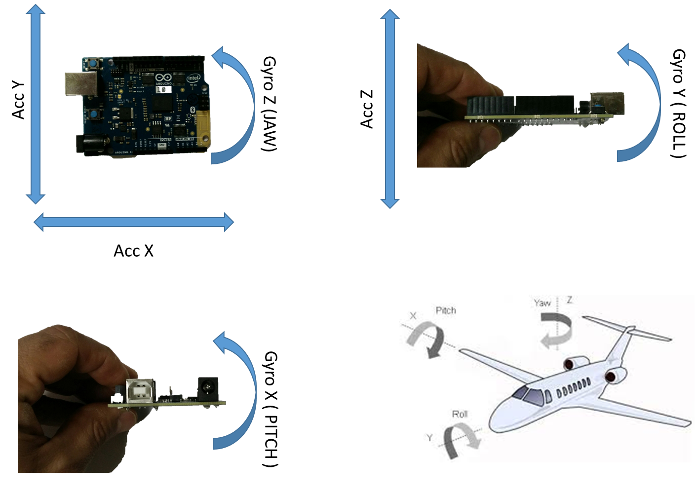
Figura 1 – Ejes detectables de movimiento.
EJERCICIOS
En estos cuatro ejercicios exploraremos las diferentes funciones del Arduino 101, en lo referente a sensores de movimiento, comunicación Bluetooth BLE y uso de la memoria no volatil del sistema.
Para todos los ejercicios utilizaremos este programa base:
/*
 Copyright (c) 2015 Intel Corporation. All rights reserved.

 This library is free software; you can redistribute it and/or
 modify it under the terms of the GNU Lesser General Public
 License as published by the Free Software Foundation; either
 version 2.1 of the License, or (at your option) any later version.

 This library is distributed in the hope that it will be useful,
 but WITHOUT ANY WARRANTY; without even the implied warranty of
 MERCHANTABILITY or FITNESS FOR A PARTICULAR PURPOSE. See the GNU
 Lesser General Public License for more details.

 You should have received a copy of the GNU Lesser General Public
 License along with this library; if not, write to the Free Software
 Foundation, Inc., 51 Franklin Street, Fifth Floor, Boston, MA 02110-1301 USA

 Modified by Jose Nunez @ intel corporation on April 2 2016

 https://www.arduino.cc/en/Tutorial/Genuino101CurieBLEHeartRateMonitor

*/

/*
 This sketch example demonstrates how the BMI160 on the
 Intel(R) Curie(TM) module can be used to read accelerometer data
*/

#include "CurieIMU.h"
#include <CurieBLE.h>

int EXERCISE = 1;


/****************** BLE HEARTRATE GLOBALS **************************/
BLEPeripheral blePeripheral; // BLE Peripheral Device (the board you're programming)
BLEService heartRateService("180D"); // BLE Heart Rate Service

// BLE Heart Rate Measurement Characteristic"
BLECharacteristic heartRateChar("2A37", // standard 16-bit characteristic UUID
 BLERead | BLENotify, 2); // remote clients will be able to get notifications if this characteristic changes
 // the characteristic is 2 bytes long as the first field needs to be "Flags" as per BLE specifications
 // https://developer.bluetooth.org/gatt/characteristics/Pages/CharacteristicViewer.aspx?u=org.bluetooth.characteristic.heart_rate_measurement.xml

int oldHeartRate = 0; // last heart rate reading from analog input
long previousMillis = 0; // last time the heart rate was checked, in ms
/****************** END OF BLE HEARTRATE GLOBALS **************************/

void setup() {
 delay(3000);
 Serial.begin(9600); // initialize Serial communication
 pinMode(13, OUTPUT); // initialize the LED on pin 13 to indicate when a central is connected
 while (!Serial); // wait for the serial port to open
 Serial.println("SETUP...");
 // initialize device
 Serial.println("Initializing IMU device...");
 CurieIMU.begin();

 // Set the accelerometer range to 2G
 CurieIMU.setAccelerometerRange(2);

/****************** BLE HEARTRATE SETUP **************************/
 /* Set a local name for the BLE device
 This name will appear in advertising packets
 and can be used by remote devices to identify this BLE device
 The name can be changed but maybe be truncated based on space left in advertisement packet */
 blePeripheral.setLocalName("HeartRateSketch");
 blePeripheral.setAdvertisedServiceUuid(heartRateService.uuid()); // add the service UUID
 blePeripheral.addAttribute(heartRateService); // Add the BLE Heart Rate service
 blePeripheral.addAttribute(heartRateChar); // add the Heart Rate Measurement characteristic

 /* Now activate the BLE device. It will start continuously transmitting BLE
 advertising packets and will be visible to remote BLE central devices
 until it receives a new connection */
 blePeripheral.begin();
 Serial.println("Bluetooth device active, waiting for connections...");
/****************** END OF BLE HEARTRATE SETUP **************************/

 Serial.println("SETUP COMPLETE");

}

void loop() {
 switch(EXERCISE){
 case 1:
 readAndReportAccelerometer();
 break;
 case 2:
 readAndReportGyroscope();
 break;
 case 3:
 monitorHeartRate();
 break;
 }
}

float pax, pay, paz, dax, dayy, daz;
void readAndReportAccelerometer(){
 int axRaw, ayRaw, azRaw; // raw accelerometer values
 float ax, ay, az;

 // read raw accelerometer measurements from device
 CurieIMU.readAccelerometer(axRaw, ayRaw, azRaw);

 // convert the raw accelerometer data to G's
 ax = convertRawAcceleration(axRaw);
 ay = convertRawAcceleration(ayRaw);
 az = convertRawAcceleration(azRaw);

 dax = abs(ax-pax);
 dayy = abs(ay-pay);
 daz = abs(az-paz);

 if(dax>0.02 || dayy>0.02 || daz>0.02){

 // display tab-separated accelerometer x/y/z values
 Serial.print("a:\t");
 Serial.print(ax);
 Serial.print("\t");
 Serial.print(ay);
 Serial.print("\t");
 Serial.print(az);
 Serial.println();

 pax = ax;
 pay = ay;
 paz = az;
 }
}

float prev_gx, prev_gy, prev_gz, diff_gx, diff_gy, diff_gz;
float relevancyTrigger = 0.3;
void readAndReportGyroscope() {
 int gxRaw, gyRaw, gzRaw; // raw gyro values
 float gx, gy, gz;

 // read raw gyro measurements from device
 CurieIMU.readGyro(gxRaw, gyRaw, gzRaw);

 // convert the raw gyro data to degrees/second
 gx = convertRawGyro(gxRaw);
 gy = convertRawGyro(gyRaw);
 gz = convertRawGyro(gzRaw);

 diff_gx = abs(prev_gx-gx);
 diff_gy = abs(prev_gy-gy);
 diff_gz = abs(prev_gz-gz);

 if(diff_gx>relevancyTrigger || diff_gy>relevancyTrigger || diff_gz>relevancyTrigger){

 // display tab-separated gyro x/y/z values
 Serial.print("g: \t");
 Serial.print(gx);
 Serial.print("\t");
 Serial.print(gy);
 Serial.print("\t");
 Serial.print(gz);
 Serial.println( "");

 prev_gx = gx;
 prev_gy = gy;
 prev_gz = gz;
 }

}

void monitorHeartRate(){
 // listen for BLE peripherals to connect:
 BLECentral central = blePeripheral.central();

 // if a central is connected to peripheral:
 if (central) {
 Serial.print("Connected to central: ");
 // print the central's MAC address:
 Serial.println(central.address());
 // turn on the LED to indicate the connection:
 digitalWrite(13, HIGH);

 // check the heart rate measurement every 200ms
 // as long as the central is still connected:
 while (central.connected()) {
 long currentMillis = millis();
 // if 200ms have passed, check the heart rate measurement:
 if (currentMillis - previousMillis >= 200) {
 previousMillis = currentMillis;
 updateHeartRate();
 }
 }
 // when the central disconnects, turn off the LED:
 digitalWrite(13, LOW);
 Serial.print("Disconnected from central: ");
 Serial.println(central.address());
 }
}

void updateHeartRate() {
 /* Read the current voltage level on the A0 analog input pin.
 This is used here to simulate the heart rate's measurement.
 */
 int heartRateMeasurement = analogRead(A0);
 int heartRate = map(heartRateMeasurement, 0, 1023, 0, 100);
 if (heartRate != oldHeartRate) { // if the heart rate has changed
 Serial.print("Heart Rate is now: "); // print it
 Serial.println(heartRate);
 const unsigned char heartRateCharArray[2] = { 0, (char)heartRate };
 heartRateChar.setValue(heartRateCharArray, 2); // and update the heart rate measurement characteristic
 oldHeartRate = heartRate; // save the level for next comparison
 }
}

float convertRawAcceleration(int aRaw) {
 // since we are using 2G range
 // -2g maps to a raw value of -32768
 // +2g maps to a raw value of 32767

 float a = (aRaw * 2.0) / 32768.0;

 return a;
}

float convertRawGyro(int gRaw) {
 // since we are using 250 degrees/seconds range
 // -250 maps to a raw value of -32768
 // +250 maps to a raw value of 32767

 float g = (gRaw * 250.0) / 32768.0;

 return g;
}
EJERCICIOS #1 y 2 – ACELERÓMETRO Y GIROSCOPIO
En este ejercicio realizaremos lecturas del acelerómetro y del giroscopio y mostraremos el resultado en el monitor serial.
A su vez, implementamos una lógica de detección de cambios relevantes que nos permitirá observar con mayor claridad los cambios ocurridos en las medidas de los sensores.
PASO 1 – Cargue el programa del tutorial en su Arduino 101
PASO 2 – Utilizando la Figura 1 como guía, verifique en el Monitor Serial del IDE ARDUINO si los ejes mencionados son correctos para el acelerómetro (x,y,z)
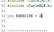
PASO 3 – Modifique el programa, comentando la línea 32 para darle el valor de 2 a la variable EXERCISE.
PASO 4 – Cargue el programa modificado al Arduino 101 y verifique los ejes de giro tal y como se ilustran en la Figura 1
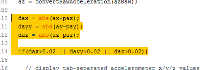
PASO 5 – Preste atención a las líneas de la 110 a la 114; esta es la lógica de detección de cambios relevantes. Trate de explicarla.
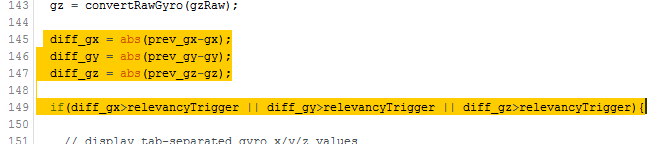
PASO 6 – Ahora preste atención a las líneas de la 145 a la 149, es una implementación más limpia / autoexplicable de la lógica de detección de cambios relevantes. Trate de explicarla.
PASO 7 – Reto: Modifique la lógica de detección de cambios relevantes para que detecte cualquier cambio.
EJERCICIO #3 – SIMULACION DE BLE HEARTBEAT SERVICE
En este ejercicio vamos a utilizar la comunicación Bluetooth/BLE para simular un mecanismo de detección de ritmo cardiaco y graficarlo en el celular.
Para esto necesitaremos un celular con capacidad BLE. En este descargaremos una aplicación llamada «nRF Toolbox» la cual hace una implementación de varios esquemas de servicio BLE. Utilizaremos entonces el servicio «HRM» (Heart Rate Monitor) para graficar datos provenientes del Arduino 101.
PASO 1 – Instale nRF Toolbox en su celular
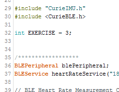
PASO 2 – Re-configure el sketch base de este tutorial para ejecutar el ejercicio 3. En la línea 32 modifique la variable EXERCISE para que tenga un valor de 3.
PASO 3 – Descargue el programa hacia la placa Arduino 101
PASO 4 – Abra el Monitor Serial (SHIFT + CTRL + M)
PASO 5 – En su celular, abra la aplicación «nRF Toolbox» y abra el servicio HRM. Allí pulse el botón «Connect» y elija «HeartRateSketch»
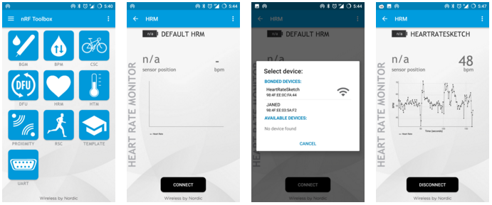
PASO 6 – Observe cómo se grafican los datos
PASO 7 – Explicación
Esta simulación toma el valor de uno de los puertos analógicos del Arduino 101 (A0) y envia los datos a través de un servicio BLE estandard de tipo «Heart Rate Service». Si se deja el pin A0 de la placa sin conexion, este tendrá valores «aleatorios» que serán graficados igual.
Recursos Adicionales
https://www.arduino.cc/en/Guide/Arduino101
http://www.intel.com/content/www/us/en/wearables/wearable-soc.html
![]()
Comentarios